Transport of water–air interface
This first test case is important since it validates the capacity of the numerical method to treat simple advection of an interface between pure fluids without creating spurious oscillations on pressure or velocity profiles. Input files for this test are available in ./libTests/referenceTestCases/PUEq/1D/transports/interfaceWaterAir/. The corresponding uncommented line in ECOGEN.xml is:
<testCase>./libTests/referenceTestCases/PUEq/1D/transports/interfaceWaterAir/</testCase>
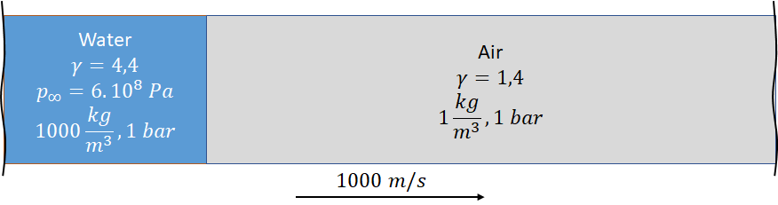
Fig. 64 Initial condition for 1D advection of water–air interface.
The initial characteristics of the run are:
Characteristic |
Value |
|---|---|
dimension |
1 m |
Mesh size |
800 |
interface position |
0.3 m |
boundary conditions |
non-reflecting |
final solution time |
0.7 ms |
solution printing frequency |
0.025 ms |
precision |
1st order |
In the default test case, the computation is performed with a 1st order scheme. We compare this solution with those obtained using the 2nd order scheme with THINC limiter [SX14].
Fig. 65 Advection of a water–air interface. Visualization using Paraview software.