Generating Meshes
ECOGEN is able to generate its own Cartesian meshes (see section Cartesian mesh), but for structured non Cartesian or unstructured meshes, as seen in section Unstructured mesh, an external mesh software is required to generate mesh files.
Mesh files with Gmsh
ECOGEN can use mesh files for single- or multi-core computations generated with the open-source Gmsh software [GR09] with some specific precautions when editing the geometry file (.geo). Only the MSH file format version 2 can be used in the current released version 5.0 of ECOGEN.
To export your mesh to the version 2, either:
Download older Gmsh binaries before the new mesh file format was introduced, such as version 3.0.6 or lower: http://gmsh.info/bin/.
Use latest version of Gmsh but export your mesh file to the version 2, for more information see the tutorial Export Gmsh mesh to version 2 file format.
Here are the restrictions that should be used when generating a geometry with Gmsh:
Each part of the domain occupied by the fluid should correspond to a physical surface or a physical volume which is attributed to the value 10.
Each boundary condition must correspond to a physical line or a physical surface. The values are successively taken from 1 to maximum 9. This is an important point that will be used to define boundary conditions with physical treatment in the initialConditions.xml input file described in section InitialConditions.xml.
Below is presented an example.
Generating a nozzle unstructured mesh
Consider the geometry file of a simple nozzle depicted below:
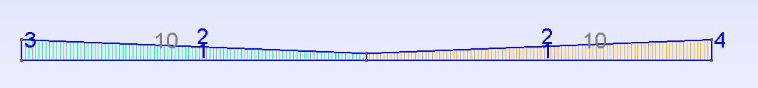
Fig. 10 Example of geometrical data file – nozzle2D_example.geo –- for generating a mesh file with .msh format using Gmsh software and usable with ECOGEN.
This corresponds to the geometry file available in ECOGEN/libMeshes/nozzles/nozzle2D_example.geo.
The computational domain is a nozzle, the mesh is unstructured with quadrangles. In that case, one should take care that the fluid surface is defined by the value 10 and that 4 boundary conditions are set with the following numbering:
Symmetrical axis: 1 (boundAxis = 1)
Wall: 2 (boundWall = 2)
Injection using stagnation state: 3 (boundInlet = 3)
Imposed pressure: 4 (boundOutlet = 4)
The corresponding initialCondition.xml file should then contains for example the following markups:
<!-- LIST OF BOUNDARY CONDITIONS -->
<boundaryConditions>
        <boundCond name="axis" type="symmetry" number="1" />
        <boundCond name="wall" type="wall" number="2" />
        <boundCond name="inlet" type="inletTank" number="3">
                <dataInletTank p0="2.e5" T0="187.5"/>
        </boundCond>
        <boundCond name="outlet" type="outletPressure" number="4">
                <dataOutletPressure p0="1.e5"/>
        </boundCond>
</boundaryConditions>
This corresponds to initialization of a nozzle connected to a tank on the left and to an outflow at imposed pressure to the right.