Split physical domains for unstructured meshes
ECOGEN is able to initialize fluid domains according to geometrical physical domains for Gmsh unstructured mesh (see Generating Meshes). Of course, it is also possible to initialize the computational domain with predefined type domain as described in the section InitialConditions.xml. However, in this tutorial, we will focus on how to initialize fluid physical domains in ECOGEN according to geometrical domains defined in the geometry file of Gmsh .geo.
For the purpose of this tutorial, we will use a 2D single-phase shock tube of 1m length and 1m height (more information about this setup can be found at Test cases). The tube is filled with air (\(\rho = 1.225 \, kg /m^3\)) initially at rest, the left chamber pressure is \(P_L = 5 \, bar\) and the right chamber pressure is fixed at \(P_R = 1 \, bar\).
Geometry and mesh
The 2D tube is defined by a 1x1 square. To design the initial interface between the left and right chamber we create two points on the upper and lower part (Point(5) and Point(6)) of the domain, that are connected by Line(7):
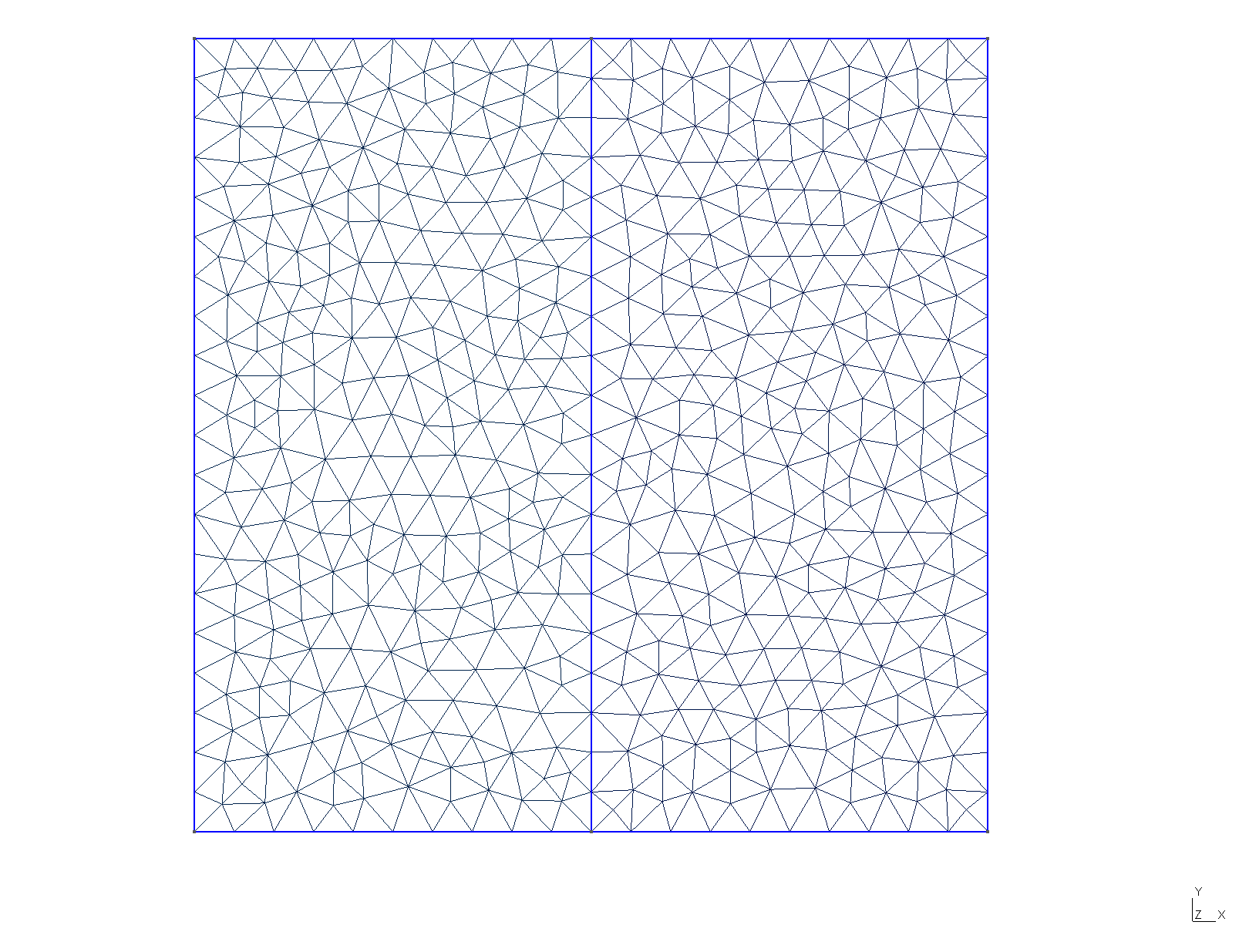
Fig. 14 Geometry and mesh (triangular elements) of the 2D shock tube on Gmsh software.
The complete geometry configuration file (.geo) is the following:
//Mesh size
dx = 0.05;

// Physical domains number
walls = 1;
leftChamber = 2;
rightChamber = 3;

// Geometry definition
Point(1) = {0, 0, 0, dx};
Point(2) = {1, 0, 0, dx};
Point(3) = {1, 1, 0, dx};
Point(4) = {0, 1, 0, dx};
Point(5) = {0.5, 0, 0, dx};
Point(6) = {0.5, 1, 0, dx};

Line(1) = {1, 4};
Line(2) = {4, 6};
Line(3) = {6, 3};
Line(4) = {3, 2};
Line(5) = {2, 5};
Line(6) = {5, 1};

Line(7) = {5,6}; // Interface between chambers

// Boundary conditions
Physical Line(walls) = {1, 2, 3, 4, 5, 6};

// Left Chamber domain
Line Loop(8) = {1, 2, -7, 6};
Plane Surface(9) = {8};
Physical Surface(leftChamber) = {9};

// Right chamber domain
Line Loop(10) = {3, 4, 5, 7};
Plane Surface(11) = {10};
Physical Surface(rightChamber) = {11};
Setup of the test case
Let’s start with the main.xml file. We use an VTK output mode with time control set to iterations and a CFL number of 0.8:
<?xml version = "1.0" encoding = "UTF-8" standalone = "yes"?>
<computationParam>
        <run>shockTubeUnstructured</run>
        <outputMode format="VTK" binary="false" precision="15"/>
        <timeControlMode iterations="true">
                <iterations number="100" iterFreq="10"/>
                <physicalTime totalTime="1e-3" timeFreq="5.e-5"/>
        </timeControlMode>
        <computationControl CFL="0.8"/>
</computationParam>
To solve this flow we use the model Euler with air considered as ideal gas. Thus, the model.xml file is:
<?xml version = "1.0" encoding = "UTF-8" standalone = "yes"?>
<model>
        <flowModel name="Euler"/>
        <EOS name="IG_air.xml"/>
</model>
Reading of the unstructured mesh is done through the mesh.xml file:
<?xml version = "1.0" encoding = "UTF-8" standalone = "yes"?>
<mesh>
        <type structure="unStructured"/>
        <unstructuredMesh>
                <file name="libMeshes/myMeshFolder/tube2d.msh"/>
        </unstructuredMesh>
</mesh>
All that remains to be done is to initialize the chambers with the corresponding fluid states. To this end, we define two physicalDomains of type entireDomain, one for each chamber. The link between the physical domains of the geometry file .geo and ECOGEN is made by the attribute physicalEntity. As given above on the .geo file, the left chamber has the physical entity number 2 and the right chamber has the number 3. Therefore, the initialConditions.xml file is:
<?xml version = "1.0" encoding = "UTF-8" standalone = "yes"?>
<CI>
    <!-- LIST OF GEOMETRICAL DOMAINS  -->
    <physicalDomains>
        <domain name="leftChamber" state="leftChamber" type="entireDomain" physicalEntity="2"/>
        <domain name="rightChamber" state="rightChamber" type="entireDomain" physicalEntity="3"/>
    </physicalDomains>

    <!-- LIST OF BOUNDARY CONDITIONS -->
    <boundaryConditions>
        <boundCond name="walls" type="wall" number="1" />
    </boundaryConditions>

    <!--  LIST OF STATES  -->
    <state name="leftChamber">
        <material type="fluid" EOS="IG_air.xml">
            <dataFluid density="1.225" pressure="5.e5">
                <velocity x="0." y="0." z="0."/>
            </dataFluid>
        </material>
    </state>

    <state name="rightChamber">
        <material type="fluid" EOS="IG_air.xml">
            <dataFluid density="1.225" pressure="1.e5">
                <velocity x="0." y="0." z="0."/>
            </dataFluid>
        </material>
    </state>
</CI>
Add the new test case to the main input file ECOGEN.xml: <testCase>./libTests/myTest/</testCase>.
Run the test case simulation with XX cores:
./ECOGEN
mpirun -np XX ECOGEN
Important
Be aware to partition the mesh file with the corresponding number of cores used for the simulation if parallel computation is desired. Gmsh pre-treatment attribute GMSHPretraitement of the mesh.xml file might be set to true in this case.
Results
Initially, the configuration of the shock tube is as follows:
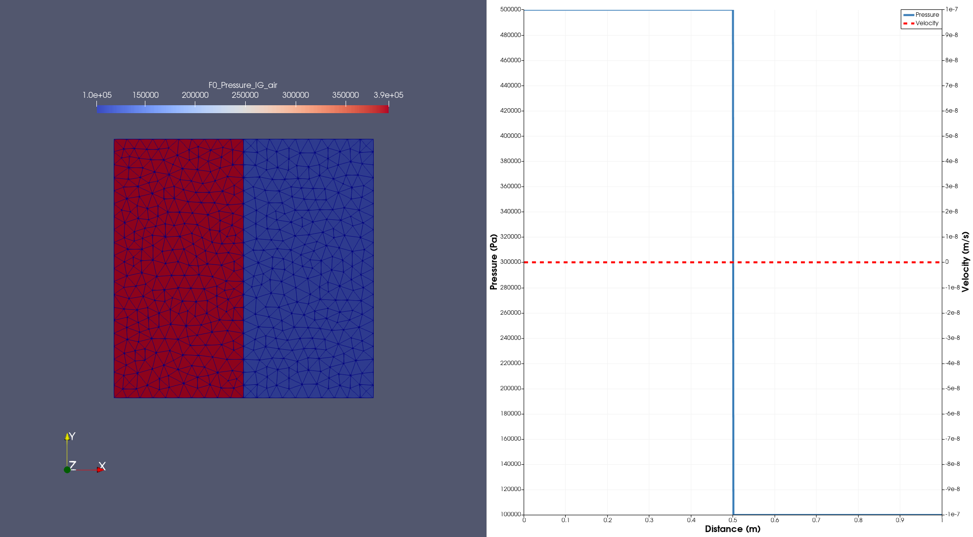
Fig. 15 Pressure visualization (left) and 1D plot of pressure and velocity along the length of the tube (right) at the initial time. Visualization using Paraview software.
It is clearly visible that the addition of the line along the interface makes it possible to obtain a mesh with a straight separation at this location. In the absence of this line, the initialization of the fluid states using a halfSpace leads to an initial interface deformed by the cells position:
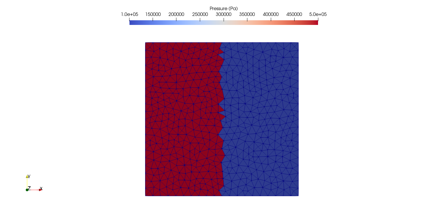
Fig. 16 Pressure visualization at the initial time. Visualization using Paraview software.
Of course, for this test case configuration, it is possible to obtain an equivalent result without declaring two physical domains in the geometry file. By keeping the middle line of the geometry file, the straight separation is ensured and it is therefore possible to define in the initialConditions.xml file an entireDomain domain for the left chamber and a halfSpace domain located at \(x = 0.5 \, m\) with a positive direction for the right chamber.
However, it can be particularly interesting to use an initialization of the fluid states with the definition of the physical domains from the geometry, in case the fluid regions are too complex to define with the predefined ECOGEN domains.
After few timesteps, the flow is the following:
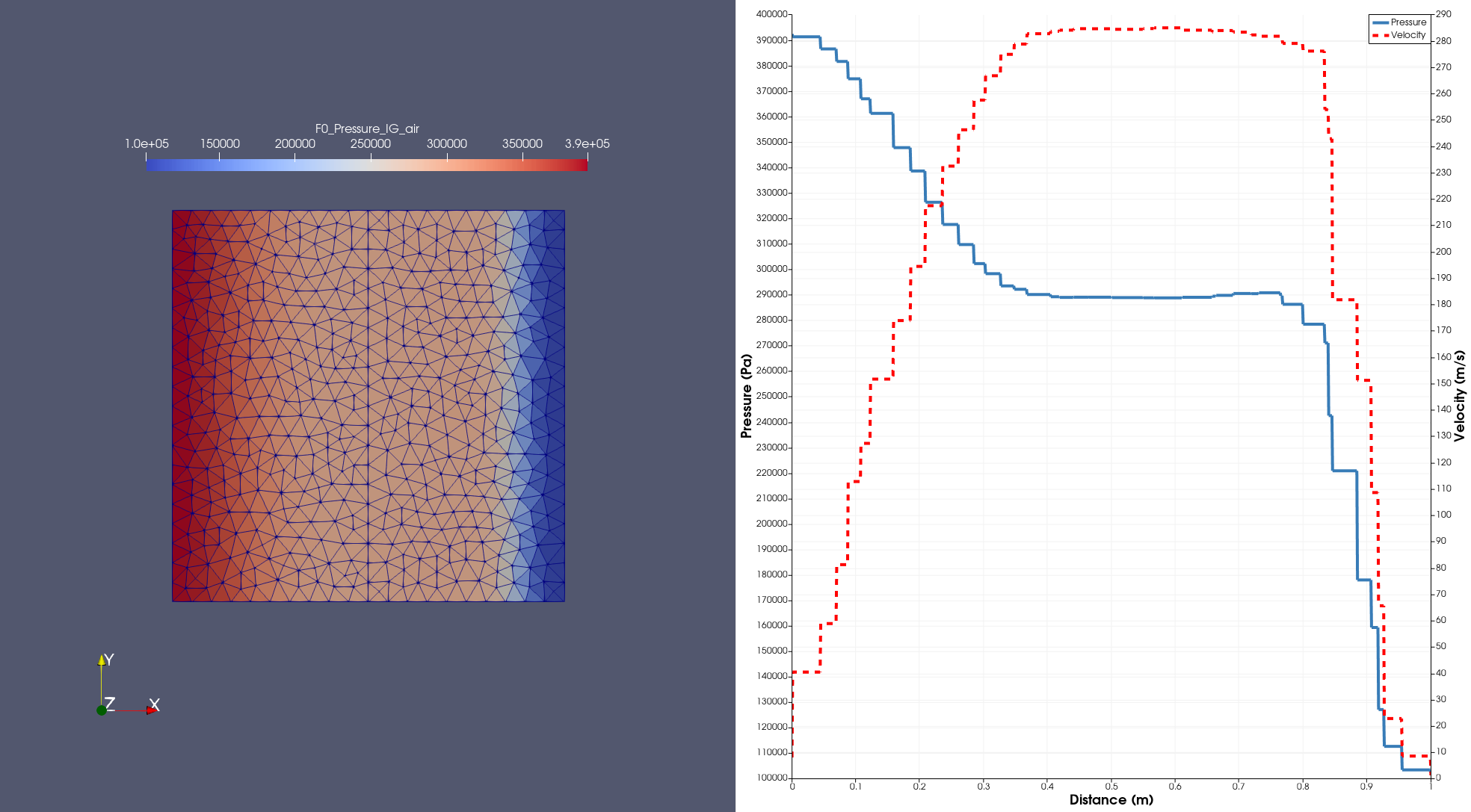
Fig. 17 Pressure visualization (left) and 1D plot of pressure and velocity along the length of the tube (right) after few timesteps. Visualization using Paraview software.