Restart a simulation with mesh mapping
In ECOGEN it is possible to initialize a simulation with the result of a previous simulation performed on a different mesh and/or a different number of cores. The main use case is to accelerate the convergence to the steady state by using a previous simulation performed on a coarse mesh, but it can also be used to restart a simulation on a different number of cores.
Overview
In this tutorial, this mesh mapping method is used to fasten convergence towards steady state of a subsonic flow in a convergent-divergent nozzle. To build our test case, we consider the following reference test case in the ECOGEN.xml file:
<testCase>libTests/referenceTestCases/euler/2D/nozzles/lowMachSmoothCrossSection/</testCase>
In this test case, originally from [LMNS13], a subsonic flow of liquid water is injected into the nozzle as shown in Fig. 35. At the inlet, the mass flow rate is imposed as well as the total stagnation enthalpy using the pressure and density. At the outlet, the pressure is fixed. These boundary conditions lead to a subsonic flow in the whole nozzle.
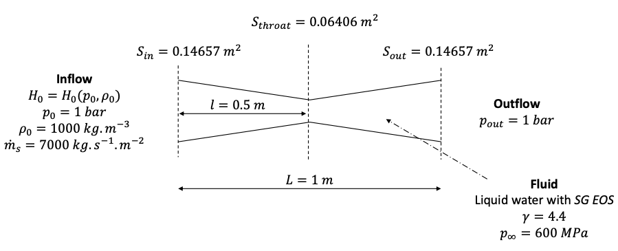
Fig. 35 Setup for the subsonic flow within the convergent-divergent nozzle.
Since the cross-section variation along the nozzle is smooth, a 1D mesh is considered and the numerical scheme is adapted to include the impact on the flow of the upper and lower walls of the nozzle using the method described in [LMNS13].
This can be done by adding the following node to the model.xml file:
<geometry smoothCrossSection1d="true"/>
Note that by default a low-Mach preconditioning technique (see [LMNS13]) is defined in this test case to properly capture the flow at the throat. Since the same effect can be obtained with a very fine mesh and our goal is to provide a configuration demonstrating the interest of the mesh mapping, this option is disabled:
<lowMach state="false"/>
In this tutorial, we will first run a simulation on a coarse mesh until the steady state is reached. Then, this simulation will be used to initialize another simulation on a finer mesh. The proper behavior of the mesh mapping will be checked and a discussion of the time saved with the mapping is provided.
Run a simulation on a coarse mesh
Note
In the following, in order to demonstrate that steady state solution obtained with the mesh mapping method corresponds to the exact solution, a coarse mesh of Nx = 1 000 and a fine one of Nx = 10 000 cells are used. Simulations with these meshes can be quite long, therefore for testing purpose the reader is advised to test with Nx = 100 and Nx = 1 000 cells.
To run the simulation on two cores, use:
mpirun -np 2 ECOGEN
To check that steady state is reached, flow quantities can be checked using a visualization software such as Paraview.
Note that it might be useful to compare the massflow between the inlet and outlet of the nozzle to make sure steady state is reached.
Massflow rate can be recorded with the <recordBoundaryFlux> node in the main.xml file, for more information about this, see the tutorial Gmsh example and extraction of mass-flow rate.
Setup the restart with mesh mapping
Now that we have a steady state result obtained on a coarse mesh, we will use it to initialize our simulation on a fine mesh of about Nx = 10 000 cells. First, make sure to change the name of the result folder to avoid erasing the simulation on the coarse mesh. This can be done by changing the following line in main.xml:
<run>euler2DnozzleLowMachSmoothCrossSection_fine</run>
Now we need to change the mesh to the fine one and add the mesh mapping option with the adequate parameters. It needs to be provided with the results folder of the previous coarse mesh simulation, the file to restart to and the mesh file used before. Taking into consideration these remarks, the mesh.xml file is modified as follow:
<?xml version="1.0" encoding="UTF-8"?>
<mesh>
<type structure="unStructured"/>

  <unstructuredMesh>
    <file name="libMeshes/nozzles/smoothNozzle2DforLowMach_Nx10000_10cpu.msh"/>
    <parallel GMSHPretraitement="true"/>

    <meshMappingRestart
      resultFolder="euler2DnozzleLowMachSmoothCrossSection_coarse"
      restartFileNumber="1000"
      meshFile="libMeshes/nozzles/smoothNozzle2DforLowMach_Nx1000_2cpu.msh"
    />

  </unstructuredMesh>
</mesh>
The simulation is ready to be run, in this case the mesh is partitioned on 10 cores. Therefore ECOGEN must be executed using:
mpirun -np 10 ECOGEN
Results
To determine how much time is saved thanks to the mesh mapping, one can also run the simulation on the fine mesh Nx = 10 000 using basic initial conditions, this run corresponds to test number 3 in the table below. The initial run on the coarse mesh corresponds to test number 1 and the run with the mesh mapping is the run number 2.
Test |
Description |
Mesh (Nx) |
Nb of CPUs |
Simulation time (h:m:s) |
Cumulative time (h:m:s) |
|---|---|---|---|---|---|
1 |
Direct run |
1000 |
1 |
0:36:29 |
0:36:29 |
2 |
Mapping on test 1 |
10000 |
10 |
4:54:15 |
5:30:44 |
3 |
Direct run |
10000 |
10 |
9:23:36 |
9:23:36 |
In Fig. 36 and Fig. 37, we can clearly see that that the same steady state is reached whether the mesh mapping is used or not (see Test 2 and 3) and that an excellent agreement with the exact solution is observed. From the cumulative simulation time reported in table above, it can be noticed that the mesh mapping method reduces the simulation time to steady state by more than 50% compared to the direct run when no mesh mapping is used (Test 3) and this even if the initial solution obtained on the coarse mesh is still far from the exact solution.
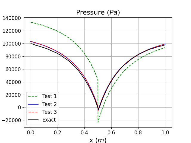
Fig. 36 Pressure distribution along the nozzle length
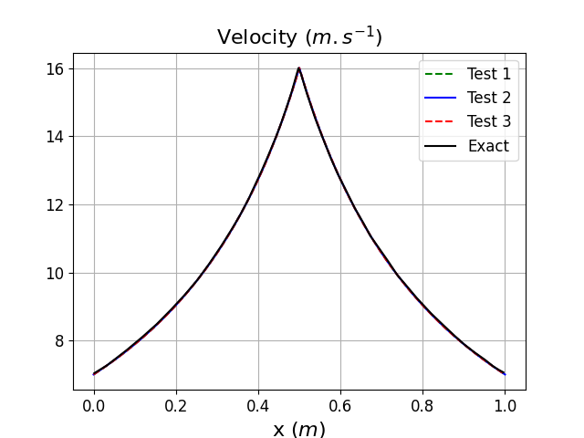
Fig. 37 Velocity distribution along the nozzle length